Hi Scott,
Usually Drive Step/Dir inputs can be connected directly to KFLOP but that depends on the drive interface requirements. KFLOP can sink +5V signals to GND in a open collector mode providing nearly a full 5V signal to the drive. When switching open the KFLOP pin can rise to ~3.85V providing only ~ 1.15V to the drive which in most cases will be low enough to not be driven (most LEDs take 1.4V to conduct). See:
You can feed back any Fault signal from the drive back to KFLOP and monitor the signals with a User Program and disable all the KFLOP Axes if a Fault is detected. If the drives have Encoder Outputs then another option would be to feed back position so KFLOP can monitor and plot position errors. This also has the advantage of being able to recover after an axis disable or fault without loss of position. However KFLOP itself only has single ended encoder inputs so that may be a consideration.
HTH
Regards
TK
| Group: DynoMotion |
Message: 11861 |
From: cnc_machines |
Date: 7/6/2015 |
| Subject: Re: KFlop and Servo Drives |
|
Thanks Tom, I will go ahead without the breakout board and see how it works.
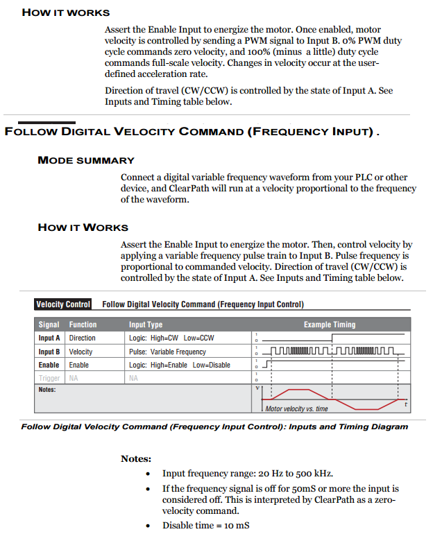
One other question. My spindle drive uses a PWM signal to control. I am planning on using a user program run when "S" is initiated in KMotionCNC. I would pass the spindle speed variable in do some math and modulate a pulse to control the speed.
Can PWM be done on any of the KFlop pins? If not could I do this with a loop in the program turning the pin on and off? The input frequency is 20 HZ to 500 kHZ. Would the Kflop have an issue modulating a pin at this frequency?
Thanks,
Scott
|
|
|
@@attachment@@
|
| Group: DynoMotion |
Message: 11863 |
From: Tom Kerekes |
Date: 7/6/2015 |
| Subject: Re: KFlop and Servo Drives [1 Attachment] |
Hi Scott,
That is actually a Step and Direction input not a PWM input. The first step would be to interface it and control it the same as any Step and Direction Axis.
Regards TK
| Group: DynoMotion |
Message: 11912 |
From: cnc_machines |
Date: 7/20/2015 |
| Subject: Re: KFlop and Servo Drives |
|
Tom,
Just hooking up the servos and will be running in opened collector mode. According to the wiring diagram you send I will hook the +5 volt up to one of the KFlops +5 pins, and then ground using one of the general purpose IO (3.3V).
I just want to double check, I should be good using any IO - I dont have to plug in to one of the 5V tolerant pins?
Thanks,
Scott
|
|
| Group: DynoMotion |
Message: 11914 |
From: Tom Kerekes |
Date: 7/20/2015 |
| Subject: Re: KFlop and Servo Drives |
Hi Scott,
Only specific pins are wired to KFLOP Hardware Step/Dir Generators and can be used as Step/Dir outputs. See:
and
Make a simple diagram of what you intend to do and we will check it for you.
Regards TK
| | | |